OSSC latency tester
Introduction
Since firmware 0.79, OSSC is able to measure display latency and strobe length (on low-persistence displays) using an external sensor and "white box" test pattern. Measurement can be made either using internally generated 480p@60Hz timing, or with a real source in any processing mode.
Sensor requirements and connection
In general, the sensor should be build with a phototransistor or photodiode (optionally using a transistor driver) to drive down a signal line when light intensity exceeds a suitable threshold. Below is described one of the easiest and cheapest implementation with minimal amount of components:
- SFH 300 phototransistor
- 150kohm 0603 SMD resistor
- A pair cable long enough to reach from OSSC to display edges (e.g. speaker or telephone cable)
- Some form of case
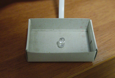
The first task is to find a suitable case for phototransisor which prevents external light affecting the sensor once it faces a display. Below is an example case built from a matchbox:
Next up a pair cable is soldered on the phototransistor legs (long one is emitter), after which sensor itself is complete.
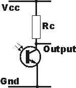
When the sensor is connected to OSSC, a common emitter phototransistor circuit is formed:
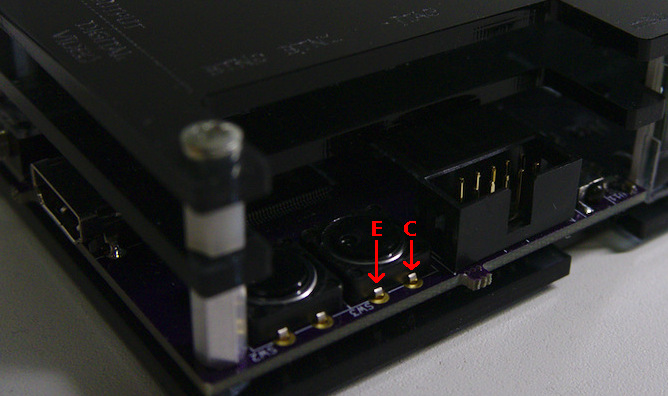
The wires from phototransistor legs are connected in parallel to BTN1 terminals (corresponding to "Output" and "Gnd" in above circuit diagram) on the PCB (either side is fine, although bottom is usually more convenient solder point):
BTN1's pull-up resistor R43 acts as "Rc" in the circuit and sets sensor threshold. The resistor must be exchanged to one with more suitable resistance for the sensor (does not affect button functionality). Typically 100k-200k is a good range, although higher resistance may provide higher sensitivity and faster rise/fall time. If you plan on using a potentiometer, make sure it is connected in series with a fixed (e.g. 10k) resistor to avoid accidentally shorting output to Vdd.
Usage
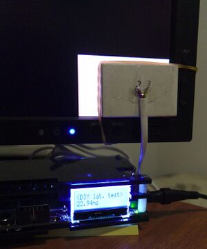
With OSSC boot-up pattern or a real source on the display, navigate to "<DIY lat. test>" on Post-processing menu. Then select pattern box position (top-left/center/bottom-right) using LEFT/RIGHT, and press OK to confirm. If display panel refresh rate matches input refresh rate, latency is typically uniform across all positions. If panel refresh rate is higher than input (e.g. 120Hz OLED TVs), bottom-right position has the lowest latency. When pattern box is rendered on screen, place the sensor on it and press OK on the remote. The pattern disappears for a moment, and returns with measured latency shown on the character LCD display. If a strobe is detected, its length (<1ms glitches are filtered out) is displayed after the latency result. Press OK to repeat measurement, or EXIT to exit latency testing mode. When testing with real sources, make sure input mode is not switched while in latency tester mode. When latency tester is not used, the sensor should be covered as triggering is registered as BTN1 press in normal mode.


