These series of quick notes are meant as stand alone tibdits of interesting data we find along while developing and polishing MDFourier. For the full documentation and the rest of the notes, please visit http://junkerhq.net/MDFourier.
One of the uses of MDFourier is to evaluate how flat the frequency response of audio equipment it.
I just acquired a Toslink <-> Coaxial converter for this project, since I wasn’t able to capture audio from HDMI enabled FPGA systems in order to compare them with MDFourier, but my audio card only has SPDIF coaxial in.
In order to provide reliable recordings, we need to know if all this hardware in the audio capture chain does not affect the audio signal. In order to do this, an already made MDFourier recording is used, and although any such file will suffice, we typically use a CD system. In this case a Sega CD audio file will be used to demonstrate the procedure.
The basic idea is to take the audio file, reproduce it and then record it again. When we compare the original recording against the copy we just made, differences must be minimal. At the very least, we should get a flat response as close to zero as possible.
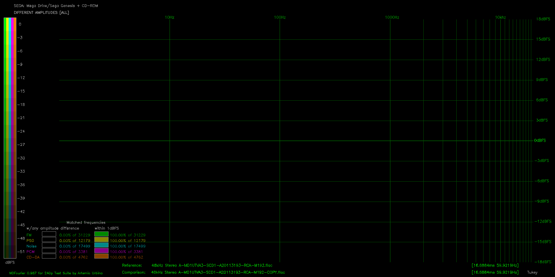
In order to give a baseline, here is the output MDFourier gives when comparing a file against itself:

This would be an ideal case, no differences found and matches are all 100% and of course, this never happens on the field.
In this scenario, we have several pieces of equipment that can modify the signal, and unfortunately we have to test them all at once. The path starts with a Blu ray player that will be used to play back the audio file from an USB drive, and then it will output the signal via HDMI. Next, the HDFury will convert that signal to TOSLINK and this will be fed into the converter and transformed into coaxial. Finally the coaxial will be connected to my audio capture card.
The capture card offers the option to use the internal or external clock, and we will test both.
I started with the external clock option, since my intuition told me that the recording should follow the source clock. The next image shows the results of the recordings, both at 48kHz and compared in the range 20Hz to 20kHz.
The results were good, at least no discernible differences at this scale, and the report says everything was matched with differences lower than 1dBFS.
We can of course be pedantic and check how it looks zoomed in, as the following image demonstrates.
One should understand that the zoom range used is 0.01dBFS, which for all purposes is ridiculously small and imperceptible, but it exists even when this was a fully digital recording. Of course, it went through several pieces of hardware. The CD-DA audio is always flat, but the other signals is where we find such small changes.
The next step was to compare the internal vs external clock, and see if that affects the recording at all. The same system but without CD-ROM was used for the following tests.
To my surprise, using the internal clock under this conditions was terribly noisy against all what I had read on the net this far. So I will stick to the SPDIF clock for recordings using this audio chain.
Even the phase was completely modified!
For reference, here is the same graph created from the recordings while using the external clock:
While I was at it, I also used a different chain. In this other case, I used HDMI to analog conversion, provided by an HDFury Nano, which has a headphone out.
As you can see, the results are way less flat and have a lot more noise. It isn’t a bad conversion, since everything is well below 3dBFS, but the difference is huge when compared to the pure digital counterpart.
This process can be used to compare audio amplifiers, upscalers, switchers, and any other equipment you might have in your audio chain. I hope you found it as fascinating as I do.