Difference between revisions of "XRGB-1"
(Created page with 'The first device in the line of XRGB upscan converters. It has four dip switches for changing configurations, and potentiometers to adjust colors and brightness. == Dip...') |
(→Outputs) |
||
| (18 intermediate revisions by 2 users not shown) | |||
| Line 1: | Line 1: | ||
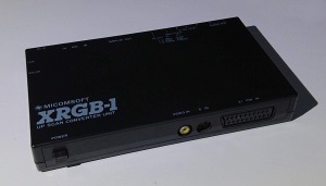
| + | [[File:xrgb-1front.jpg|300px|thumb|right|XRGB-1 Front]] | ||
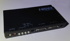
| + | [[File:xrgb-1back.jpg|300px|thumb|right|XRGB-1 Back]] | ||
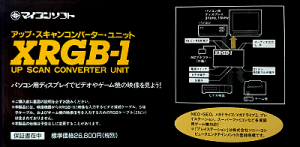
| + | [[File:Xrgb1box.png|300px|thumb|middle|XRGB-1 Box]] | ||
The first device in the line of [[XRGB]] [[upscan]] converters. It has four dip switches for changing configurations, and potentiometers to adjust colors and brightness. | The first device in the line of [[XRGB]] [[upscan]] converters. It has four dip switches for changing configurations, and potentiometers to adjust colors and brightness. | ||
| + | |||
== Dip switches == | == Dip switches == | ||
| Line 18: | Line 22: | ||
|- | |- | ||
|Normal / Narrow | |Normal / Narrow | ||
| − | |Control aspect ratio | + | |Control aspect ratio (*) |
|} | |} | ||
| + | |||
| + | (*) note that only V2.2 PCB has DIP switch for Normal / Narrow, the V1.1 PCB only has three DIP switches. | ||
| + | |||
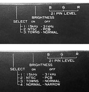
| + | [[File:Xrgb1dipswitches.jpg]] | ||
== Specifications == | == Specifications == | ||
| Line 36: | Line 44: | ||
* RCA stereo out | * RCA stereo out | ||
| + | [[File:Sanwaad-d15ne.jpg|80px|thumb|right|Sanwa<br> AD-D15NE]] | ||
| + | |||
| + | |||
| + | |||
| + | Note! 15-pin D-sub adapter to 9-pin D-sub (standard VGA connector) use Sanwa AD-D15NE (can also be used on the input). | ||
| + | <br> | ||
| + | <br> | ||
| + | <br> | ||
| + | <br> | ||
| + | <br> | ||
| + | <br> | ||
| + | <br> | ||
| + | |||
| + | == Capacitor List == | ||
| + | |||
| + | {| class="wikitable" style="text-align:left; width:20%;" | ||
| + | |- | ||
| + | ! scope=col | Ver 1.1 PCB | ||
| + | ! scope=col | Ver 2.2 PCB | ||
| + | |- | ||
| + | |SMD:<br> | ||
| + | C1 100uF/16V<br> | ||
| + | C3 100uF/16V<br> | ||
| + | C91 100uF/16V<br> | ||
| + | C98 100uF/16V<br> | ||
| + | C97 100uF/16V<br> | ||
| + | C45 100uF/16V<br> | ||
| + | C2 22uF/35V<br> | ||
| + | C59 22uF/35V<br> | ||
| + | C44 22uF/35V<br> | ||
| + | C7 47uF/16V<br> | ||
| + | C9 47uF/16V<br> | ||
| + | C75 1uF/50V<br> | ||
| + | C11 1uF/50V<br> | ||
| + | C25 10uF/16V<br> | ||
| + | C23 10uF/16V<br> | ||
| + | C24 10uF/16V<br> | ||
| + | C30 10uF/16V<br> | ||
| + | C80 10uF/16V<br> | ||
| + | C81 10uF/16V<br> | ||
| + | C82 10uF/16V<br> | ||
| + | C26 10uF/16V<br> | ||
| + | C57 10uF/16V<br> | ||
| + | C4 4.7uF/25V<br> | ||
| + | C62 4.7uF/25V<br> | ||
| + | C63 4.7uF/25V<br> | ||
| + | C60 4.7uF/25V<br> | ||
| + | C61 4.7uF/25V<br> | ||
| + | C16 4.7uF/25V<br> | ||
| + | C27 4.7uF/25V<br> | ||
| + | C12 4.7uF/25V<br> | ||
| + | |||
| + | HOLE:<br> | ||
| + | C70 470uF/16V<br> | ||
| + | C68 470uF/16V<br> | ||
| + | C72 470uF/16V<br> | ||
| + | C43 470uF/16V<br> | ||
| + | C67 100uF/10V<br> | ||
| + | C69 100uF/10V<br> | ||
| + | C71 100uF/10V<br> | ||
| + | C56 22uF/16V<br> | ||
| + | |HOLE: | ||
| + | C43 470uF/16V<br> | ||
| + | C70 470uF/16V<br> | ||
| + | C72 470uF/16V<br> | ||
| + | C68 470uF/16V<br> | ||
| + | C1 100uF/25V<br> | ||
| + | C98 100uF/25V<br> | ||
| + | C112 100uF/25V<br> | ||
| + | C45 100uF/25V<br> | ||
| + | C97 100uF/25V<br> | ||
| + | C91 100uF/25V<br> | ||
| + | C67 100uF/10V<br> | ||
| + | C69 100uF/10V<br> | ||
| + | C71 100uF/10V<br> | ||
| + | C75 1uF/50V<br> | ||
| + | C11 1uF/50V<br> | ||
| + | C4 4.7uF/50V<br> | ||
| + | C62 4.7uF/50V<br> | ||
| + | C63 4.7uF/50V<br> | ||
| + | C16 4.7uF/50V<br> | ||
| + | C27 4.7uF/50V<br> | ||
| + | C12 4.7uF/50V<br> | ||
| + | C4 4.7uF/50V<br> | ||
| + | C61 4.7uF/50V<br> | ||
| + | C60 4.7uF/50V<br> | ||
| + | C74 10uF/16V<br> | ||
| + | C73 10uF/16V<br> | ||
| + | C87 10uF/16V<br> | ||
| + | C25 10uF/16V<br> | ||
| + | C23 10uF/16V<br> | ||
| + | C24 10uF/16V<br> | ||
| + | C30 10uF/16V<br> | ||
| + | C26 10uF/16V<br> | ||
| + | C57 10uF/16V<br> | ||
| + | C2 22uF/35V<br> | ||
| + | C44 22uF/35V<br> | ||
| + | C59 22uF/35V<br> | ||
| + | C7 47uF/16V<br> | ||
| + | C9 47uF/16V<br> | ||
| + | C56 22uF/16V<br> | ||
| + | |} | ||
| + | |||
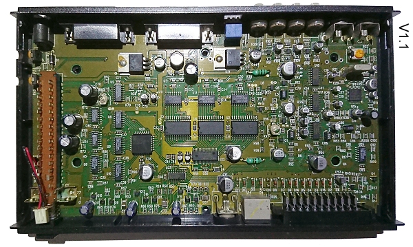
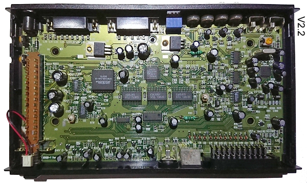
| + | Note! the bigger 100uF are the ones that leak first (V1.1 C97,54), V2.2 seems less susceptible for leaking caps. | ||
| + | |||
| + | [[File:Xrgb1pcb11.jpg]] | ||
| + | [[File:Xrgb1pcb22.jpg]] | ||
| + | |||
| + | == Power Adapter == | ||
| + | |||
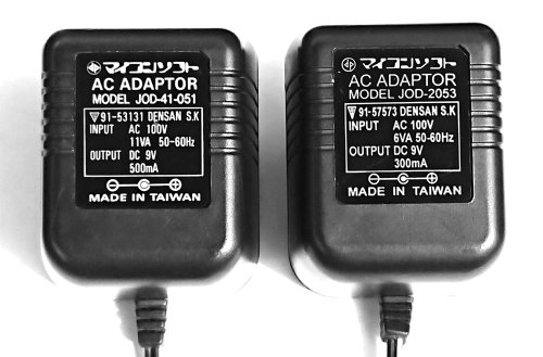
| + | There are two known variations shipped in the box, the 500mA version seemed to been with the earlier ones and 300mA with the later revisions. | ||
| + | |||
| + | JOD-41-051 (91-53131) 500mA<br> | ||
| + | JOD-2053 (91-57573) 300mA | ||
| + | |||
| + | [[File:poweradapterxrgb1models.jpg]] | ||
== External links == | == External links == | ||
| + | |||
| + | [http://www.retrosampling.se/Temp/XRGB_MANUALS/Micomsoft%20XRGB-1%20-%20Manual.pdf MANUAL (JP)]<br> | ||
[http://www.ncsx.com/www/ncs1201/xrgb-1.htm NCSX XRGB-1 page] | [http://www.ncsx.com/www/ncs1201/xrgb-1.htm NCSX XRGB-1 page] | ||
| + | |||
| + | [[Category:Upscan Converters]] | ||
Latest revision as of 18:52, 10 August 2018
The first device in the line of XRGB upscan converters. It has four dip switches for changing configurations, and potentiometers to adjust colors and brightness.
Contents
Dip switches
| Values | Description |
|---|---|
| 15 kHz / 31 kHz | Adjust output scan rate |
| NTSC / PCB | 75 ohm / 220 ohm setting |
| FM Towns /Normal | Special setting for FM towns computer |
| Normal / Narrow | Control aspect ratio (*) |
(*) note that only V2.2 PCB has DIP switch for Normal / Narrow, the V1.1 PCB only has three DIP switches.
Specifications
Inputs
Outputs
- RGB in 15-pin D-sub (for older Japanese monitors, can be connected to VGA via special cable)
- RCA stereo out
Note! 15-pin D-sub adapter to 9-pin D-sub (standard VGA connector) use Sanwa AD-D15NE (can also be used on the input).
Capacitor List
| Ver 1.1 PCB | Ver 2.2 PCB |
|---|---|
| SMD: C1 100uF/16V HOLE: |
HOLE:
C43 470uF/16V |
Note! the bigger 100uF are the ones that leak first (V1.1 C97,54), V2.2 seems less susceptible for leaking caps.
Power Adapter
There are two known variations shipped in the box, the 500mA version seemed to been with the earlier ones and 300mA with the later revisions.
JOD-41-051 (91-53131) 500mA
JOD-2053 (91-57573) 300mA
