Difference between revisions of "Koryuu"
(first draft - saving work) |
(further editing) |
||
| Line 1: | Line 1: | ||
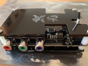
| + | [[File:Koryuu-unit-front.jpg|300px|thumb|right|Koryuu front]] | ||
| + | [[File:Koryuu-unit-back.jpg|300px|thumb|right|Koryuu back]] | ||
'''PAGE UNDER CONSTRUCTION''' | '''PAGE UNDER CONSTRUCTION''' | ||
| Line 43: | Line 45: | ||
== AV Inputs == | == AV Inputs == | ||
| + | |||
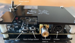
| + | [[File:Koryuu-unit-front-lab.jpg|300px|thumb|right|Inputs and switches on the front of the Koryuu]] | ||
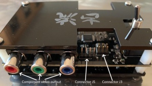
| + | [[File:Koryuu-unit-back-lab.jpg|300px|thumb|right|Output and additional I/O on the back of the Koryuu]] | ||
Koryuu has two AV inputs. The currently selected input can be selected by pressing the input change button, which is the button on the right of the unit. The input signal can be 240/288p or 480/576i (NTSC/PAL). | Koryuu has two AV inputs. The currently selected input can be selected by pressing the input change button, which is the button on the right of the unit. The input signal can be 240/288p or 480/576i (NTSC/PAL). | ||
| Line 58: | Line 63: | ||
Koryuu has a single component video output. The device does not scale, deinterlace or affect frame rate, so whatever signal goes in will be transcoded and output via the component video out. The device has no frame buffer so no input lag is added. | Koryuu has a single component video output. The device does not scale, deinterlace or affect frame rate, so whatever signal goes in will be transcoded and output via the component video out. The device has no frame buffer so no input lag is added. | ||
| − | == Buttons == | + | == Buttons and controls == |
| − | The device has two buttons on the front of the unit. | + | The device has two buttons on the front of the unit and a power switch. The power switch simply toggles the unit off and on. |
=== Input Change button === | === Input Change button === | ||
| Line 81: | Line 86: | ||
== Status LEDs == | == Status LEDs == | ||
| + | |||
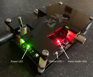
| + | [[File:Koryuu-unit-leds-lab.jpg|300px|thumb|right|LEDs on the Koryuu]] | ||
The Koryuu Transcoder has four LED (light emitting diodes) that illuminate to indicate various modes of operation. In the picture above we can see the location of these LEDs. | The Koryuu Transcoder has four LED (light emitting diodes) that illuminate to indicate various modes of operation. In the picture above we can see the location of these LEDs. | ||
| Line 92: | Line 99: | ||
== Other connectors == | == Other connectors == | ||
| − | J3 – Serial connector for capturing debugging information and development. J5 is located just to the | + | J3 – Serial connector for capturing debugging information and development. J5 is located just to the right of the component video output when viewing the unit from behind. |
J5 – This connector can be used with suitable USP ASP programmers to load new firmware (see the picture in the firmware upgrade section for pin orientation). The pin-out for this connector is as follows. | J5 – This connector can be used with suitable USP ASP programmers to load new firmware (see the picture in the firmware upgrade section for pin orientation). The pin-out for this connector is as follows. | ||
Revision as of 15:38, 8 July 2020
PAGE UNDER CONSTRUCTION
Contents
Introduction
Koryuu is an affordable composite and S-Video to component video transcoder/converter designed by Ari Sundholm (MegaAri).
Designed particularly with OSSC users in mind, Koryuu can be connected to the AV2 input on the OSSC to add composite and S-video compatibility. It can also be used as a general purpose transcoder for CRT displays.
The device is compatible with many flat panel displays too, but since the Koryuu does not upscale or deinterlace, it is usually best to it with another scaler, such as an OSSC, in this situation.
Currently, the device has open source firmware but a closed source hardware design though this may change in future.
Specifications
- Designed for use with OSSC, no additional transcoder/converter required
- Composite and S-Video in, Component video out
- 7.5 IRE option
- PAL 60 supported
- Firmware updatable (requires USB Asp or similar programmer)
- Uses the same PSU as OSSC, no chance of mixing them up and damaging either unit
- Plexiglass enclosure
- Connect Composite and S-Video at the same time, no problems
- Option button for additional features added in future firmware updates.
Availability
Pre-assembled units and accessories are available from VideoGamePerfection (EU).
More information & discussion
Power
Koryuu uses the same 5 volt power supply as OSSC. The specifications are as follows:-
DC 5 Volt output with at least 1 Amp current. The tip must be 2.1 x 5.5mm and center positive.
Do not use a power supply rated for AC output, or a power supply rated higher than 5 volts DC, doing so can damage the Koryuu.
AV Inputs
Koryuu has two AV inputs. The currently selected input can be selected by pressing the input change button, which is the button on the right of the unit. The input signal can be 240/288p or 480/576i (NTSC/PAL).
Composite video
The yellow RCA connector on the front of the unit on the right hand side accepts a standard composite video (CVBS) signal suppled by a single RCA cable. Both PAL and NTSC formats are supported.
S-Video
A S-Video device outputting a separate luma and chroma signal can be connected to the S-video input using a standard S-video cable. Both PAL and NTSC formats are supported.
Output
Koryuu has a single component video output. The device does not scale, deinterlace or affect frame rate, so whatever signal goes in will be transcoded and output via the component video out. The device has no frame buffer so no input lag is added.
Buttons and controls
The device has two buttons on the front of the unit and a power switch. The power switch simply toggles the unit off and on.
Input Change button
By pressing the input change button (see the image above) the user can cycle through the active inputs. There are currently four input modes:-
- Composite video (CVBS)
- Composite video + pedestal (7.5 IRE mode)
- S-Video (YC)
- S-Video + pedestal (7.5 IRE mode)
When powered on, the Koryuu defaults to input mode 1. Press the Input change button to cycle through the available modes. When in mode 4, pressing the input change button again will cycle back to mode 1.
7.5 IRE mode may be required for certain sources (e.g video cassettes). If the picture is too light, try 7.5 IRE mode.
Option button
The option button is for future firmware updates and features and as of firmware 1.0 it does not do anything.
Status LEDs
The Koryuu Transcoder has four LED (light emitting diodes) that illuminate to indicate various modes of operation. In the picture above we can see the location of these LEDs.
Power LED – This LED will illuminate green whenever the Koryuu is powered on.
Option LED – This LED will illuminate red whenever the Koryuu’s option mode is enabled. This is expected to be utilised in future firmware revisions.
Input mode LEDs – There are two LEDs located at this position. When the unit is in composite video input mode, the bottom LED will illuminate red. When the unit is in S-Video input mode, the top-most LED will illuminate green.
Other connectors
J3 – Serial connector for capturing debugging information and development. J5 is located just to the right of the component video output when viewing the unit from behind.
J5 – This connector can be used with suitable USP ASP programmers to load new firmware (see the picture in the firmware upgrade section for pin orientation). The pin-out for this connector is as follows.
(to do)
Known issues / limitations
- Interlace signal field reversal – Intermittently, the Koryuu will reverse the fields in an interlace signal (odd field will be switched with the even field).
This can cause compatibility issues with the OSSC or other undesirable effects on CRT displays. Usually, power cycling the unit or switching to a different input will cure the problem.
The issue is still under investigation and will hopefully be resolved in a future firmware update.
Firmware Upgrade
The current release firmware is version 1.0 and comes pre-flashed on all Koryuu’s sold.
Koryuu transcoder firmware flash procedure
Prerequisite Requirements
- Koryuu transcoder and PSU
- Suitable USB ASP programmer
- USB drivers for the ASP programmer Windows drivers are available here
- Ribbon cable and 10 to 6 pin adapter for ASP (AVRisp)
- Windows 10 PC with USB port
- Khazama AVR Programmer software
- Complied Firmware file
Note - Firmware needs to have been flashed before the unit is functional. If powered up without firmware, only the PWR LED next to the power switch will light up. This will simply indicate that the unit is receiving power, but tells nothing else. All units sold by VideoGamePerfection.com come with firmware pre-flashed.
Connection and firmware programming
1. Download and install the Khazama AVR Programmer software to your PC
2. Connect the USB ASP programmer to the PC
3. If you have never used the programmer on your PC before, install the drivers from this link . If you need help with this, see this page. Scroll down to the heading "Best & Easy method" and follow the instructions from there.
4. Connect the ribbon cable and adapter to the USB ASP
5. Connect the other end of the ribbon cable to the Koryuu transcoder via the header shown in the picture below. Pin 2 is voltage or VCC so orientate the AVRisp accordingly. Double check this before proceeding.
(add picture here)
6. Check again the orientation of the ribbon cable. Pin 2 is voltage and must match pin 2 as shown on the picture above.
7. Power on the Koryuu transcoder.
8. Start the Khazama AVR Programmer software. The program window shown below should appear.
(add picture here)
9. On the drop down box under "AVR:" ensure that the correct AVR is selected. ATMEGA328P is the AVR in our recommended programmer.
10. Open the file menu and choose "Load FLASH file to buffer". Using the standard Windows file requester, navigate to the hex file provided, click on it and choose "Open".
11. Open the command menu and choose "Write flash buffer to chip". A successful programming should only take a second or two.
Note – On some PCs you may see a message that says "Error setting USBASP ISP Clock". This can safely be ignored (just click on OK to dismiss it).
The Koryuu is now updated.
Firmware Revision History
Version 1.0 – Release


