Difference between revisions of "RetroTINK2X"
(added image) |
(added basic usage info) |
||
| Line 42: | Line 42: | ||
=== Composite video === | === Composite video === | ||
| − | The yellow connector on the front of the unit on the right hand side accepts a standard composite video (CVBS) signal suppled by a single RCA cable. Both PAL and NTSC formats are supported. | + | The yellow RCA connector on the front of the unit on the right hand side accepts a standard composite video (CVBS) signal suppled by a single RCA cable. Both PAL and NTSC formats are supported. |
=== S-Video === | === S-Video === | ||
| Line 61: | Line 61: | ||
RetroTINK 2X has a single HDMI video output. The connector is a mini HDMI that outputs 480p/576p in line-doubled mode or input resolution in passthrough mode. | RetroTINK 2X has a single HDMI video output. The connector is a mini HDMI that outputs 480p/576p in line-doubled mode or input resolution in passthrough mode. | ||
| + | |||
| + | == Basic usage == | ||
| + | |||
| + | RetroTINK is controlled using the two pushbuttons on the left of the unit. A series of small LEDs indicate what mode the device is in. | ||
| + | |||
| + | === Input Switch === | ||
| + | |||
| + | By pressing the input switch (see the image above) the user can cycle through the active inputs. If the image appears black and white, it is likely that the wrong input is selected. | ||
| + | |||
| + | === Mode Switch === | ||
| + | |||
| + | By pressing the mode switch (labelled "smoothing On/Off" in the image above) the user can cycle through the three output modes. These are discussed in more detail in the next section. | ||
| + | |||
| + | === Output Modes === | ||
| + | |||
| + | RetroTINK 2X has three different output modes. | ||
| + | |||
| + | '''Mode 1 – Transcoding Only (all LEDs off)''' – In this mode the RetroTINK will perform digitisation only. Whatever resolution is fed in will be output. Note that many HDMI televisions do not support 240p input via HDMI at all. This mode is useful for users who wish to use the RetroTINK 2X with a HDMI to VGA adapter to feed the signal into legacy analogue video equipment such as BVM monitors, or for chaining the RetroTINK 2X through another scaler such as the [[OSSC]]. | ||
| + | |||
| + | '''Mode 2 – Line Doubling (2x LED on)''' – In this mode, a 240p signal will be converted to a 480p signal. A 480i signal will also be converted to a 480p signal using a simple "bob" deinterlacing technique. Beware of using the RetroTINK 2X’s deinterlacer on sources that display static graphics or text for a long period of time. RetroTINKs deinterlacer produces a constant flickering effect, this can cause image retention/burn in to occur faster than normal. | ||
| + | |||
| + | '''Mode 3 – Doubling + Smoothing (both LEDs on)''' – In this mode the RetroTINK 2X will apply an image smoothing filter to the output. This filter can smooth some of the jagged edges that appear in classic video games console graphics output. Setting this option is entirely a matter of taste, there is no right or wrong setting. | ||
| + | |||
| + | The picture below shows an example of how the smoothing filter changes the image. | ||
Revision as of 18:33, 28 September 2018
Contents
Introduction
RetroTINK 2X is an affordable composite, S-Video, component video and analogue audio to HDMI transcoder/converter designed by Mike Chi.
Rather than being an all-purpose line doubler like the OSSC, RetroTINK 2X aims to be a highly affordable device that can function either as a basic transcoder or line doubler on its own, or as a device integrated into a more complex setup.
Specifications
- Video inputs: component, S-video and composite
- Video formats: 240p/480i, 288i/576i, NTSC and PAL color
- Video sync recovery and regeneration for non-standard sources (e.g., SNES)
- Output: miniHDMI at 480p/576p (line-doubled mode) or input resolution (pass-thru mode)
- Audio: 24-bit stereo
- Power: microUSB
- Ultra-low latency: less than 5 scanlines (83 microseconds)
- Optional smoothing filter
- Plexi-glass enclosure
Availability
Pre-assembled units and accessories will soon be available from VideoGamePerfection.com (EU) and CastleMania Games (US).
More information & discussion
Power
RetroTINK 2X requires an external DC power supply. Since the unit uses a Mini USB connector as a DC power supply input, any powered USB port can be used to supply voltage. If your television has a USB port then this can usually be used to power the device. If you require a separate power supply unit for the device then a suitable power supply can be purchased from VideoGamePerfection.com or from any good electronics retailer.
Do not use a power supply rated for AC output, or a power supply rated higher than 5 volts DC, doing so can damage the RetroTINK 2X.
AV Inputs
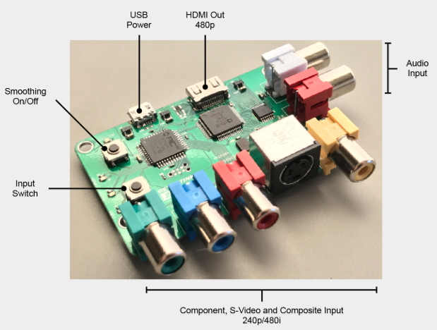
RetroTINK 2X has three AV inputs. The currently selected input can be selected by pressing the input switch, which is the bottom of the two push button switches on the left of the unit. The input signal can be 240/288p or 480/576i (NTSC/PAL).
Important - Ensure that only one powered input is connected at any one time. For example, if devices are connected to S-Video and composite inputs at the same time, only the device currently in use can be powered, the other device must be powered off.
Composite video
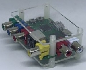
The yellow RCA connector on the front of the unit on the right hand side accepts a standard composite video (CVBS) signal suppled by a single RCA cable. Both PAL and NTSC formats are supported.
S-Video
A S-Video device outputting a separate luma and chroma signal can be connected to the S-video input using a standard S-video cable. Both PAL and NTSC formats are supported.
Component video
A standard YPBPR component video signal can be input using the 3 RCA connectors on the front of the unit. Both PAL and NTSC formats are supported. Only 15khz resolutions are supported, 480p (and higher) resolutions are not supported and will not work.
Not that it is NOT possible to input RGB video using all four RCA connectors at the same time.
Analog Audio
Connect a standard stereo analogue audio signal to the two RCA connectors on the right of the unit. This audio will be digitised and output via HDMI with the currently active video input.
Output
RetroTINK 2X has a single HDMI video output. The connector is a mini HDMI that outputs 480p/576p in line-doubled mode or input resolution in passthrough mode.
Basic usage
RetroTINK is controlled using the two pushbuttons on the left of the unit. A series of small LEDs indicate what mode the device is in.
Input Switch
By pressing the input switch (see the image above) the user can cycle through the active inputs. If the image appears black and white, it is likely that the wrong input is selected.
Mode Switch
By pressing the mode switch (labelled "smoothing On/Off" in the image above) the user can cycle through the three output modes. These are discussed in more detail in the next section.
Output Modes
RetroTINK 2X has three different output modes.
Mode 1 – Transcoding Only (all LEDs off) – In this mode the RetroTINK will perform digitisation only. Whatever resolution is fed in will be output. Note that many HDMI televisions do not support 240p input via HDMI at all. This mode is useful for users who wish to use the RetroTINK 2X with a HDMI to VGA adapter to feed the signal into legacy analogue video equipment such as BVM monitors, or for chaining the RetroTINK 2X through another scaler such as the OSSC.
Mode 2 – Line Doubling (2x LED on) – In this mode, a 240p signal will be converted to a 480p signal. A 480i signal will also be converted to a 480p signal using a simple "bob" deinterlacing technique. Beware of using the RetroTINK 2X’s deinterlacer on sources that display static graphics or text for a long period of time. RetroTINKs deinterlacer produces a constant flickering effect, this can cause image retention/burn in to occur faster than normal.
Mode 3 – Doubling + Smoothing (both LEDs on) – In this mode the RetroTINK 2X will apply an image smoothing filter to the output. This filter can smooth some of the jagged edges that appear in classic video games console graphics output. Setting this option is entirely a matter of taste, there is no right or wrong setting.
The picture below shows an example of how the smoothing filter changes the image.


