Difference between revisions of "System 16"
Jump to navigation
Jump to search
(→XRGB-3 specific settings) |
|||
| Line 43: | Line 43: | ||
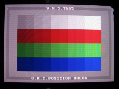
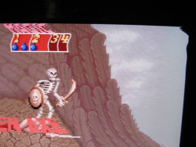
The tested PCBs showed distortion on the top 26 lines in either B0 or B1 mode as shown in the following photograph: | The tested PCBs showed distortion on the top 26 lines in either B0 or B1 mode as shown in the following photograph: | ||
| − | [[ | + | {| class="wikitable" border="1" |
| + | |- | ||
| + | |<!--column1-->[[Image:AlteredBeastCRT-Test-AFC-before.jpg|400px|thumb]] | ||
| + | |<!--column2-->[[Image:System16AFC-before.jpg|400px|thumb]] | ||
| + | |- | ||
| + | |<!--column1-->Altered beast CRT Test | ||
| + | |<!--column2-->Golden Axe demo | ||
| + | |}<!--end wikitable--> | ||
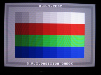
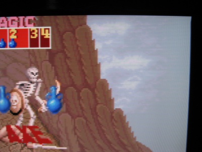
This can be fixed by setting AFC to MANUAL and changing the default value to 3. It does fix the problem completely in B0, and almost fixes it in B1 as shown below: | This can be fixed by setting AFC to MANUAL and changing the default value to 3. It does fix the problem completely in B0, and almost fixes it in B1 as shown below: | ||
| − | [[ | + | {| class="wikitable" border="1" |
| + | |- | ||
| + | |<!--column1-->[[Image:AlteredBeastCRT-Test-AFC-after-B0.jpg|400px|thumb]] | ||
| + | |<!--column2-->[[Image:System16AFC-after.jpg|400px|thumb]] | ||
| + | |- | ||
| + | |<!--column1-->Altered beast CRT Test | ||
| + | |<!--column2-->Golden Axe demo | ||
| + | |}<!--end wikitable--> | ||
| + | |||
An off/on cycle is needed sometimes after changing the AFC settings. | An off/on cycle is needed sometimes after changing the AFC settings. | ||
Revision as of 07:50, 13 January 2010
File:System16 AlteredBeast.jpg
Sega System 16
A hardware platform by Sega, uses a 16 bit 68000 processor. The edge connector on the PCB is not JAMMA compatible, an adapter is needed.
Games tested
- Altered Beast
- Golden Axe
Pinout
SOLDER SIDE                          COMP SIDE
-----------------------------------------------------
A  GND                              1   GND
B  GND                              2   GND
C  +5V                              3   +5V
D  +5V                              4   +5V
E  +12V                             5   +12V
F  CTR 2                            6   CTR 1
H                                   7
J  P2 Button 3                      8   P1 Button 3
K  P2 Button 2                      9   P1 Button 2
L  P2 Button 1                     10   P1 Button 1
M                                  11
N  PL 2 DOWN                       12   PL 1 DOWN
P  PL 2 UP                         13   PL 1 UP
R  PL 2 RIGHT                      14   PL 1 RIGHT
S  PL 2 LEFT                       15   PL 1 LEFT
T                                  16
U                                  17
V                                  18
X  1 PL START                      20   COIN 1
Y  2 PL START                      21   COIN 2
Z                                  22   TEST
a                                  23   SVC
b  SP-                             24   SP+
c  VID GN                          25   VID RED
d  SYNC                            26   VID BL
e  GND                             27   GND
f  GND                             28   GND
XRGB-3 specific settings
The tested PCBs showed distortion on the top 26 lines in either B0 or B1 mode as shown in the following photograph:
| Altered beast CRT Test | Golden Axe demo |
This can be fixed by setting AFC to MANUAL and changing the default value to 3. It does fix the problem completely in B0, and almost fixes it in B1 as shown below:
| Altered beast CRT Test | Golden Axe demo |
An off/on cycle is needed sometimes after changing the AFC settings.


