Difference between revisions of "System 16"
(→Pinout) |
(→Pinout) |
||
| Line 29: | Line 29: | ||
|C | |C | ||
|3 | |3 | ||
| − | |+5V | + | | +5V |
|- | |- | ||
| − | |+5V | + | | +5V |
|D | |D | ||
|4 | |4 | ||
| − | |+5V | + | | +5V |
|- | |- | ||
| − | |+12V | + | | +12V |
|E | |E | ||
|5 | |5 | ||
| − | |+12V | + | | +12V |
|- | |- | ||
|Counter 2 | |Counter 2 | ||
Revision as of 06:15, 14 January 2010
A hardware platform by Sega, uses a 16 bit 68000 processor. The edge connector on the PCB is not JAMMA compatible, an adapter is needed. There are two variants of the hardware: System 16A and System 16B, currently only System 16B boards have been tested.
Contents
Pinout
| English | Setting | Default setting | |
|---|---|---|---|
| Solder side | Pin | Pin | Parts side |
| Ground | A | 1 | Ground |
| Ground | B | 2 | Ground |
| C | 3 | +5V | |
| +5V | D | 4 | +5V |
| +12V | E | 5 | +12V |
| Counter 2 | F | 6 | Counter 1 |
| H | 7 | ||
| Player 2 Button 3 | J | 8 | Player 1 Button 3 |
| Player 2 Button 2 | K | 9 | Player 1 Button 2 |
| Player 2 Button 1 | L | 10 | Player 1 Button 1 |
| M | 11 | ||
| Player 2 down | N | 12 | Player 1 down |
| Player 2 up | P | 13 | Player 1 up |
| Player 2 right | R | 14 | Player 1 right |
| Player 2 left | S | 15 | Player 1 left |
| T | 16 | ||
| U | 17 | ||
| V | 18 | ||
| Player 1 start | X | 20 | COIN 1 |
| Player 2 start | Y | 21 | Coin 2 |
| Z | 22 | Test | |
| a | 23 | Service | |
| Speaker - | b | 24 | Speaker + |
| Green | c | 25 | Red |
| Sync | d | 26 | Blue |
| Ground | e | 27 | Ground |
| Ground | f | 28 | Ground |
XRGB-2 specific settings
As with all arcade boards, the 220 ohm setting needs to be set because signal lines are higher than with game consoles. Just flip the switch to the PCB setting or adjust levels from your SuperGUN if available.
The image is offset to the left with the default settings, this can be fixed by moving the H-POS value to 0 from the default 4.
XRGB-3 specific settings
As with all arcade boards, the 220 ohm setting needs to be set because signal lines are higher than with game consoles. To do this change 21ピン入力終端 from 75 オーム (75 ohm) to 220 オーム (220 ohm) under the オプション (Options) menu on the XRGB-3.
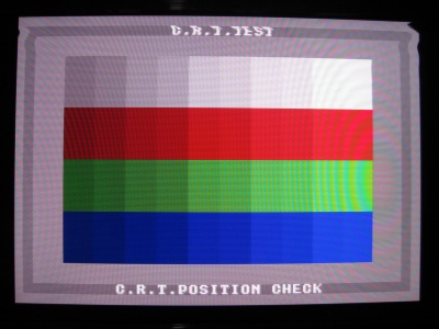
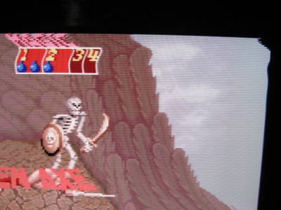
The tested PCBs showed distortion on the top 26 lines in either B0 or B1 mode as shown in the following photographs:
| Altered beast CRT Test | Golden Axe demo |
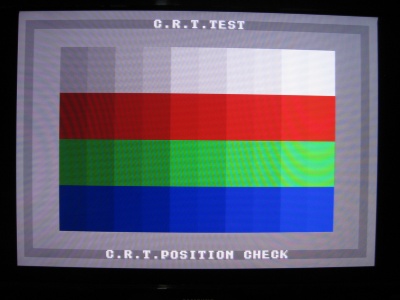
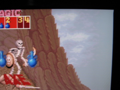
This can be fixed by setting AFC to MANUAL and changing the default value to 3. It does fix the problem completely in B0, and almost fixes it in B1 as shown below:
| Altered beast CRT Test | Golden Axe demo |
An off/on cycle is needed sometimes after changing the AFC settings.
Games tested
- Altered Beast (System 16B)
- Golden Axe (System 16B)


