Koryuu
Contents
Introduction
Koryuu is an affordable composite and S-Video to component video transcoder/converter designed by Ari Sundholm (megari).
Designed particularly with OSSC users in mind, Koryuu can be connected to the AV2 input on the OSSC to add composite and S-video compatibility. It can also be used as a general purpose transcoder for CRT displays.
The device is compatible with many flat panel displays too, but since the Koryuu does not upscale or deinterlace, it is usually best to combine it with a scaler or line doubler, such as an OSSC, in this situation.
Currently, the device has open source firmware. The PCB, case design and detailed schematics are not public at the moment, but sufficient technical information required for firmware development will be made available. There is an intention to eventually make the design files public, but the time frame has not been decided on yet.
Specifications
- Designed for use with OSSC, no additional transcoder/converter required
- Composite and S-Video in, Component video out
- 7.5 IRE option
- PAL 60 supported
- Firmware updatable (requires USB Asp or similar programmer)
- Uses the same PSU as OSSC, no chance of mixing them up and damaging either unit
- Plexiglass enclosure
- Connect Composite and S-Video at the same time, no problems
- Option button for additional features added in future firmware updates.
Availability
Pre-assembled units and accessories are available from VideoGamePerfection (EU).
More information & discussion
Power
Koryuu uses the same 5 volt power supply as OSSC. The specifications are as follows:-
DC 5 Volt output with at least 1 Amp current. The tip must be 2.1 x 5.5mm and center positive.
Do not use a power supply rated for AC output, or a power supply rated higher than 5 volts DC, doing so can damage the Koryuu.
AV Inputs
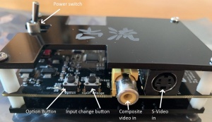
Koryuu has two AV inputs. The currently selected input can be selected by pressing the input change button, which is the button on the right of the unit. The input signal can be 240/288p or 480/576i (NTSC/PAL).
Composite video
The yellow RCA connector on the front of the unit on the left hand side accepts a standard composite video (CVBS) signal suppled by a single RCA cable. Both PAL and NTSC formats are supported.
S-Video
A S-Video device outputting a separate luma and chroma signal can be connected to the S-video input using a standard S-video cable. Both PAL and NTSC formats are supported.
Output
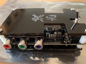
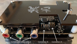
Koryuu has a single component video output. The device does not scale, deinterlace or affect frame rate, so whatever signal goes in will be transcoded and output via the component video out. The device has no frame buffer so no input lag is added.
Buttons and controls
The device has two buttons on the front of the unit and a power switch. The power switch simply toggles the unit off and on.
Input Change button
By pressing the input change button (see the image above) the user can cycle through the active inputs. There are currently four input modes:-
- Composite video (CVBS)
- Composite video + pedestal (7.5 IRE mode)
- S-Video (YC)
- S-Video + pedestal (7.5 IRE mode)
When powered on, the Koryuu defaults to input mode 1. Press the Input change button to cycle through the available modes. When in mode 4, pressing the input change button again will cycle back to mode 1.
7.5 IRE mode may be required for certain sources (e.g video cassettes). If the picture is too light, try 7.5 IRE mode.
Option button
The option button is for future firmware updates and features and as of firmware 1.0 it applies a smoothing/blur filter however this effect is not correctly implemented.
Status LEDs
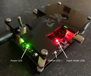
The Koryuu Transcoder has four LED (light emitting diodes) that illuminate to indicate various modes of operation. In the picture above we can see the location of these LEDs.
Power LED – This LED will illuminate green whenever the Koryuu is powered on.
Option LED – This LED will illuminate red whenever the Koryuu’s option mode is enabled. This is expected to be utilised in future firmware revisions.
Input mode LEDs – There are two LEDs located at this position. When the unit is in composite video input mode, the bottom LED will illuminate red. When the unit is in S-Video input mode, the top-most LED will illuminate green.
Other connectors
J5 – Serial connector for capturing debugging information and development. J5 is located just to the right of the component video output when viewing the unit from behind.
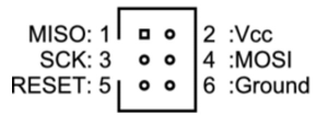
J3 – This connector can be used with suitable USP ASP programmers to load new firmware (see the picture in the firmware upgrade section for pin orientation). The pin-out for this connector is as follows.
Known issues / limitations
- Interlace signal field reversal – Intermittently, the Koryuu will reverse the fields in an interlace signal (odd field will be switched with the even field).
This can cause compatibility issues with the OSSC or other undesirable effects on CRT displays. Usually, power cycling the unit or switching to a different input will cure the problem.
The issue is still under investigation and will hopefully be resolved in a future firmware update.
Firmware Upgrade
The current release firmware is version 1.0 and comes pre-flashed on all Koryuu’s sold.
New firmware versions can be downloaded from the page here.
To program new firmware, a USB ASP programmer is required.
Recommended Programmers
- Olimex AVR-ISP-MK2
- Sparkfun's Pocket AVR Programmer
- Sparkfun's STK500 Compatible USB Programmer
- USB ASP programmer
- USB drivers for Windows are available here
Prerequisite Requirements
- Koryuu transcoder and PSU
- Suitable USB ASP programmer (see above)
- Ribbon cable and 10 to 6 pin adapter for ASP (AVRisp)
- A computer with Windows 7/8/8.1/10 with a USB port
- Compiled Firmware file
Note - Firmware needs to have been flashed before the unit is functional. If powered up without firmware, only the PWR LED next to the power switch will light up. This will simply indicate that the unit is receiving power, but tells nothing else. All units sold by VideoGamePerfection.com come with firmware pre-flashed.
Hardware setup
To avoid damage, the programmer must be set at 5V logic high level, with no power supplied to the Koryuu by the programmer (target mode off). These settings are usually configurable through jumpers on the programmer itself. The exact location varies depending on the model. Usually the jumpers are labeled according to their function. Sometimes there is a need to open up the casing of the programmer to access these jumpers.
1. Connect the USB programmer to the PC.
2. Connect the ribbon cable and adapter (if one is needed) to the programmer.
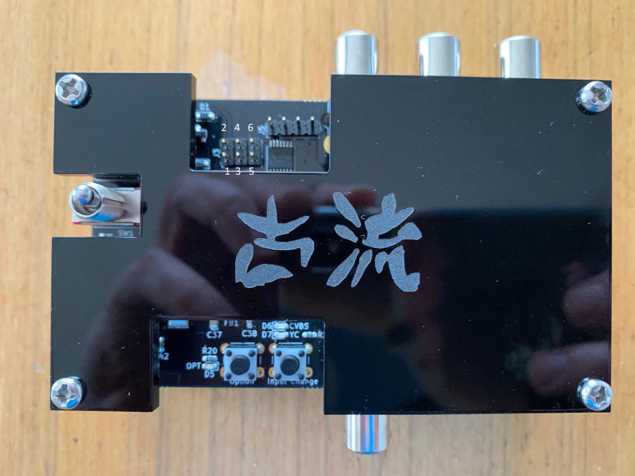
3. Connect the other end of the ribbon cable to the Koryuu transcoder via the header shown in the picture below. Pin 2 is voltage or VCC so orientate the ribbon cable accordingly. Double-check this before proceeding.
4. Check again the orientation of the ribbon cable. Pin 2 is voltage and must match pin 2 as shown on the picture above.
5. Power on the Koryuu transcoder.
6. If needed, install the driver for your programmer. If you are not sure if you have an appropriate driver installed or how to install one, see the Software setup section for details.
7. Start your programmer software. If you do not have one installed yet, see the Software setup section for instructions for one such software.
8. Flash the new firmware image using your programmer software. If you are not sure how, see the Software setup section for instructions how to do this with a particular piece of software.
The Koryuu is now updated.
Software setup (Windows 7/8/8.1/10)
This section walks us through setting up the drivers and software needed to update the firmware on your Koryuu.
There are two pieces of software required:
Install driver using Zadig
First, we need to install Zadig, which is a nifty piece of software for installing drivers for most kinds of ISP/ASP programmers. Simply point your web browser to [1], find the link labeled Download and save the executable file on your desktop (or whichever location you prefer).
You may now plug your programmer into one of the USB ports on your computer, if you have not done so already. Please see the Hardware setup section for more details.
Then, run the executable you saved previously. If an elevation (UAC) prompt pops up, accept it to continue.
The Zadig window should initially look like this:
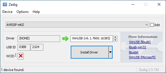
The type of your programmer may already be shown in the selection box, as in the image above (AVRISP mkII). If it is not, and you are sure it is connected, select the correct programmer from the list. Tick Options->List All Devices to show all supported devices if none show up.
Then you should choose a driver. For our purposes, selecting either the 'libusbK' or 'libusb-win32' driver should be a safe bet, the former having somewhat higher performance than the latter. Click Install Driver.
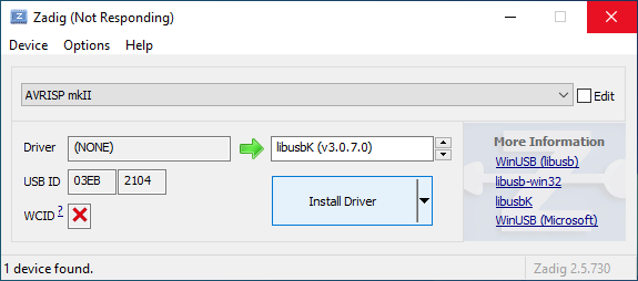
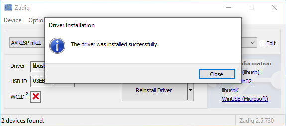
Once the installation is finished, you should see a dialog stating so.
Finally, you should see something similar to this, indicating that you now have a proper driver set up for your programmer.
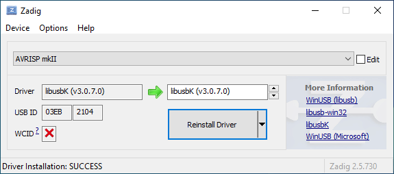
The driver setup is now complete. You may now close Zadig.
Install and run AVRDUDESS
Open the AVRDUDESS web page in your web browser and download the portable version of AVRDUDESS, which does not require any particular installation, other than extracting the archive.
Extract the archive to a location of your choosing and then open said location if Windows does not do that for you. There may be more than one file labeled Application. Choose the one with a distinct icon, named avrdudess or avrdudess.exe, and run it by double-clicking it.
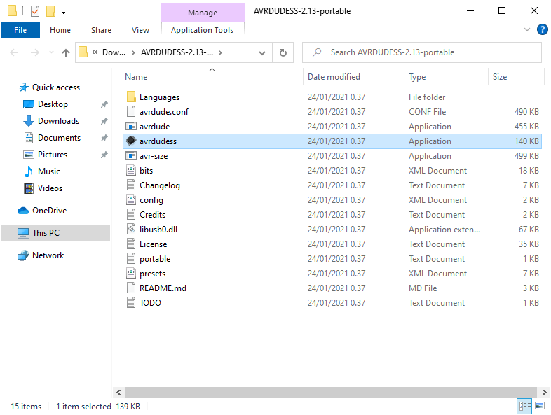
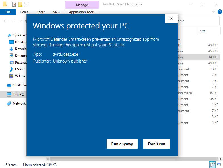
At this point you may get a Windows protected your PC box, warning that you attempted to run an unrecognized program:
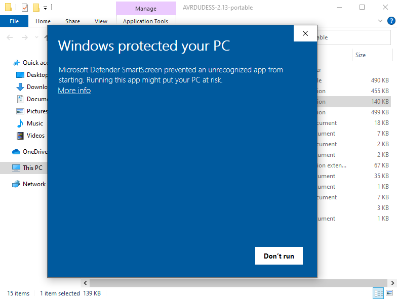
This is normal, and you should click More info, which makes a button labeled Run anyway appear. Click it.
Next, if you have not run any .Net applications before, Windows may prompt you to install the .Net Framework.
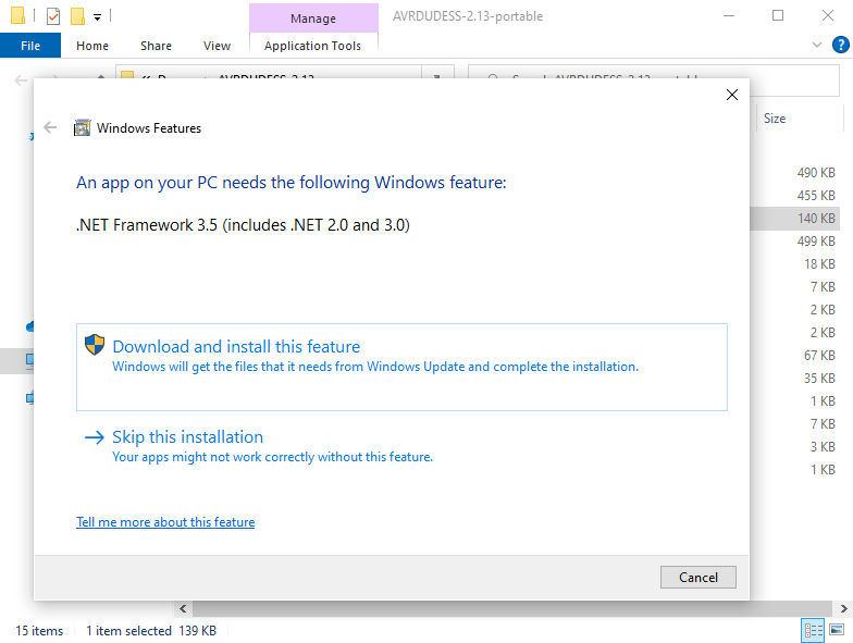
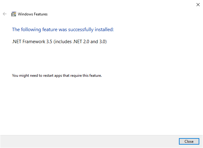
This is completely normal and safe, so allow Windows to install it. This may require accepting another elevation prompt. After the installation is done, you can try opening AVRDUDESS again.
Flash the firmware update using AVRDUDESS
Now we are ready to flash the new firmware. If you do not have AVRDUDESS open yet, open it now. The AVRDUDESS window may look a bit daunting, but fear not! We will walk through the entire process step by step.
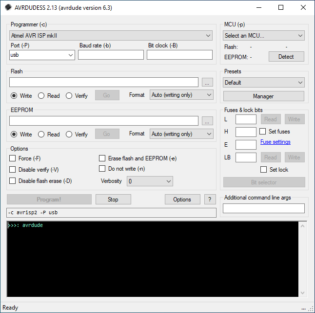
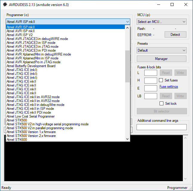
First, select the correct kind of programmer for your device from the top-left selection box.
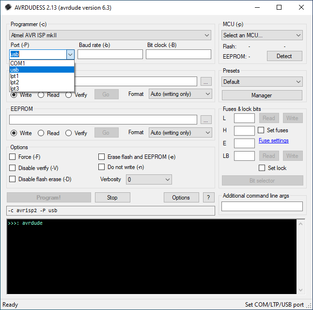
Then select the appropriate port. The port is probably going to be one of usb or COM1, but you can try each option until you find the correct one, or type the correct one in the selection box.
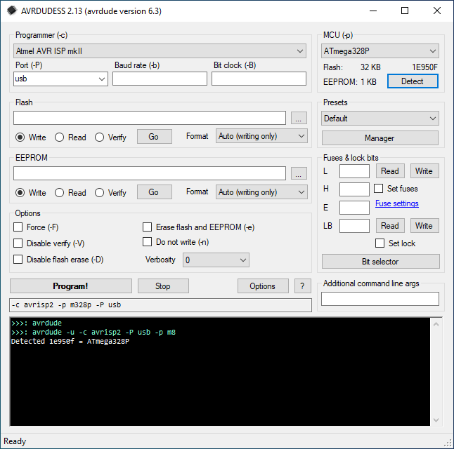
Try detecting the Koryuu on-board MCU using the Detect button. It should come up as ATmega328P.
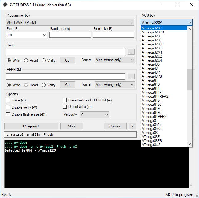
If not, select ATmega328P manually.
Within the part of the window labeled Flash, enter the path to the Koryuu firmware image or select it using the file picker dialog. Select Write on the radio selector and either Auto or Intel Hex as the format. Then click Go.
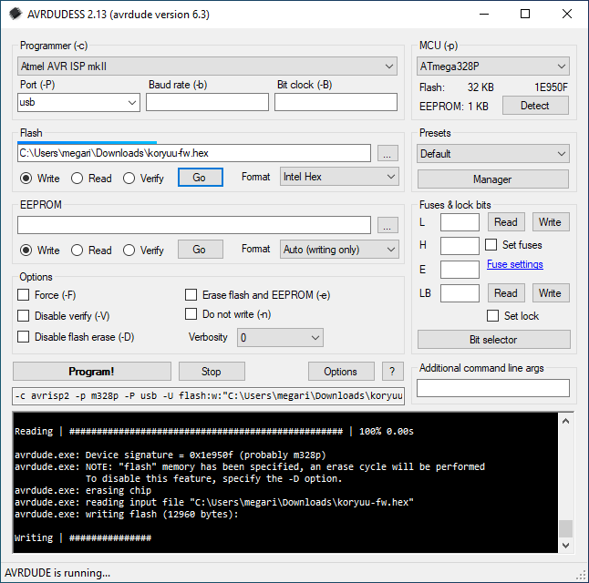
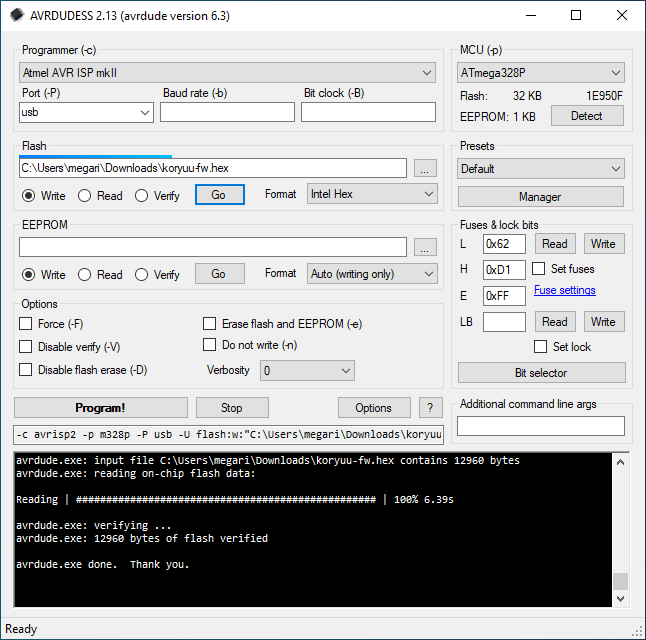
If everything went well, you should see a message like so. Please make sure that the verification part is successful.
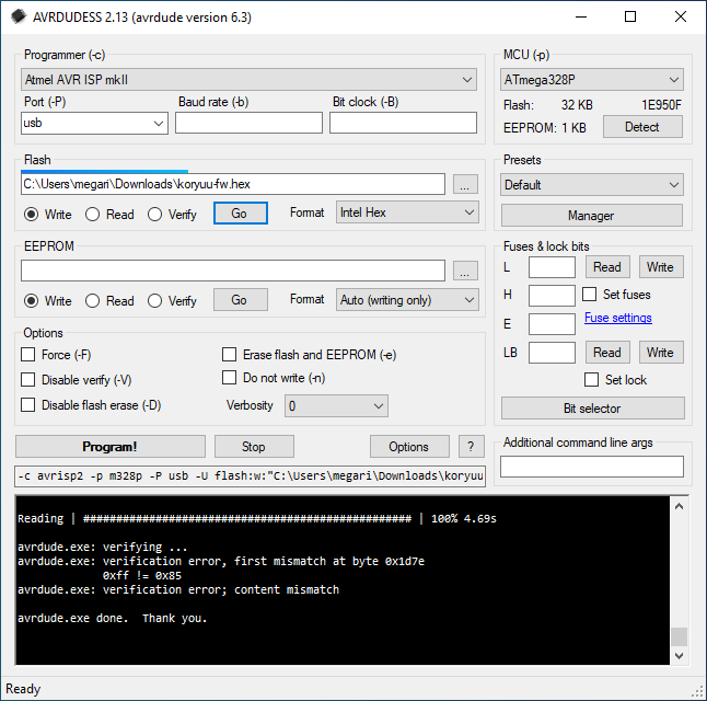
If you get a failure, such as the one below, make sure all cables are plugged correctly and the settings are as described in the Hardware setup section. Then try again.
Firmware Revision History
Version 1.0 – Release
Version 1.1-test0 – Public BETA - Bug fixes and other changes. Settings can now be saved. Improved robustness of video mode changes.
Version 1.1-test1 – Public BETA - Some further fixes to tracking of current video mode. Improvements to settings code (validation, forward compatibility). Transitions between interlaced and progressive video modes seem to be robust now.
Version 1.1-RC1 – Unofficial Release candidate 1 - Settings created by a newer firmware version will not be automagically overwritten on startup.
Version 1.1-RC2 – Unofficial Release candidate 2 - Improvements to the -ntp firmware variant.
Version 1.1-RC3 – Unofficial Release candidate 3 - Fully setup encoder chip when the currently selected input turns from on to off or vice versa.

