OSSC AV3 use AV1 RGB mod
Background
TVP7002 digitizer chip in OSSC cannot reliably lock to 240p signal with non-TTL sync using constant even field indicator, i.e. an even field is signalled to be followed by another even field. Vast majority of 240p systems (and practically all 480p/720p/1080p sources) use constant odd field indicator to denote non-interlaced/progressive signal, but there are some rare exceptions like Taito F3 system (which also has other abnormalities in sync). The only way to get these working reliably with OSSC is to connect them to AV3 input using TTL-level sync for which TVP7002 uses slightly different sync processing that ignores field indicator. This arrangement might be cumbersome for some users and is not compatible with video LPF feature. However, with two small HW modifications (to SCART cable and OSSC respectively), it is possible to have the problematic system connected to AV1 with sync getting routed to AV3. The feature is then enabled via "AV3 use AV1 RGB" option under OSSC Compatibility opt, after which logical AV3 RGBHV and RGBS inputs switch to using RGB and audio from AV1 input with only sync used from physical AV3 path. With the mod, VGA sources (HV sync) can be also connected to AV1 with a custom scart cable.
Prequisites
1. TTL-level composite / HV sync source.
Arcade boards output TTL composite sync. Unless Supergun uses a dedicated sync driver (typically sync is just routed to SCART pin directly or via series resistor), the mod is compatible. For video-level sync sources, LM1881 or similar needs to be utilized to create TTL-level sync.
2. Direct connection from source to OSSC AV1.
SCART switches do not generally switch the extra pins that are used in this mod.
HW modifications
CAUTION: proceed only if you know what you're doing. Also, don't connect anything to physical AV3 input when a customized SCART cable (as described below) is connected to physical AV1 input.
Scart cable
The cable between source and OSSC needs a bit of rewiring to be compatible the mod. Open the scart block which goes to OSSC, detach sync pin (20) and attach it to pin 12 (normally unused). If the cable type is scart-scart, mark which end is supposed to be connected to OSSC as the cable is no more symmetrical (Supergun users should get a cable dedicated just for this). If you plan on connecting a VGA source to AV1, connect hsync to pin 12 and vsync to pin 10.
OSSC
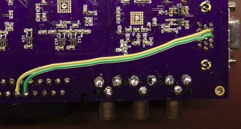
Solder 2pcs ~10cm jumper wires on the bottom of OSSC PCB as follows:
- SCART pin 12 <-> VGA pin 13
- SCART pin 10 <-> VGA pin 14
After the modification, OSSC's AV1 (scart) input has effectively 2 new pins for TTL sync:
- pin 12: HSYNC/CSYNC
- pin 10: VSYNC
Remember to enable "OSSC AV3 use AV1 RGB" option with the affected systems, and disable for others. For Taito F3, don't forget to additionally increase H-PLL pre and post coast to 4.
