RetroTINK2X
Contents
Introduction
RetroTINK 2X is an affordable composite, S-Video, component video and analogue audio to HDMI transcoder/converter designed by Mike Chi.
Rather than being an all-purpose line doubler like the OSSC, RetroTINK 2X aims to be a highly affordable device that can function either as a basic transcoder or line doubler on its own, or as a device integrated into a more complex setup.
Specifications
- Video inputs: component, S-video and composite
- Video formats: 240p/480i, 288i/576i, NTSC and PAL color
- Video sync recovery and regeneration for non-standard sources (e.g., SNES)
- Output: miniHDMI at 480p/576p (line-doubled mode) or input resolution (pass-through mode)
- Audio: 24-bit stereo
- Power: microUSB
- Ultra-low latency: less than 5 scanlines (83 microseconds)
- Optional smoothing filter
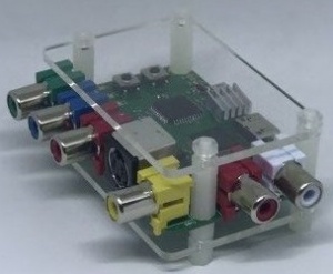
- Plexi-glass enclosure
Availability
Pre-assembled units and accessories are available from VideoGamePerfection.com (EU) and CastleMania Games (US).
More information & discussion
Power
RetroTINK 2X requires an external DC power supply. Since the unit uses a Mini USB connector as a DC power supply input, most powered USB ports can be used to supply voltage, but please ensure the port you use supplies at least one amp of current. If your television has a USB port then this can usually be used to power the device, subjet to it suppling enough current to do so. If you require a separate power supply unit for the device then a suitable power supply can be purchased from VideoGamePerfection.com or from any good electronics retailer.
Do not use a power supply rated for AC output, or a power supply rated higher than 5 volts DC, doing so can damage the RetroTINK 2X.
AV Inputs
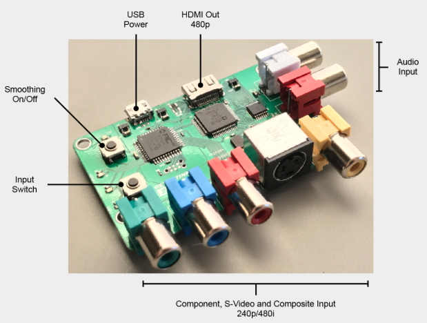
RetroTINK 2X has three AV inputs. The currently selected input can be selected by pressing the input switch, which is the bottom of the two push button switches on the left of the unit. The input signal can be 240/288p or 480/576i (NTSC/PAL).
Important - Ensure that only one powered input is connected at any one time. For example, if devices are connected to S-Video and composite inputs at the same time, only the device currently in use can be powered, the other device must be powered off.
Composite video
The yellow RCA connector on the front of the unit on the right hand side accepts a standard composite video (CVBS) signal suppled by a single RCA cable. Both PAL and NTSC formats are supported.
S-Video
A S-Video device outputting a separate luma and chroma signal can be connected to the S-video input using a standard S-video cable. Both PAL and NTSC formats are supported.
Component video
A standard YPBPR component video signal can be input using the 3 RCA connectors on the front of the unit. Both PAL and NTSC formats are supported. Only 15khz resolutions are supported, 480p (and higher) resolutions are not supported and will not work.
Not that it is NOT possible to input RGB video using all four RCA connectors at the same time.
Analog Audio
Connect a standard stereo analogue audio signal to the two RCA connectors on the right of the unit. This audio will be digitised and output via HDMI with the currently active video input.
Output
RetroTINK 2X has a single HDMI video output. The connector is a mini HDMI that outputs 480p/576p in line-doubled mode or input resolution in passthrough mode.
Basic usage
RetroTINK is controlled using the two pushbuttons on the left of the unit. A series of small LEDs indicate what mode the device is in.
Input Switch
By pressing the input switch (see the image above) the user can cycle through the active inputs. If the image appears black and white, it is likely that the wrong input is selected.
Mode Switch
By pressing the mode switch (labelled "smoothing On/Off" in the image above) the user can cycle through the three output modes. These are discussed in more detail in the next section.
Output Modes
RetroTINK 2X has three different output modes.
Mode 1 – Transcoding Only (all LEDs off) – In this mode the RetroTINK will perform digitisation only. Whatever resolution is fed in will be output. Note that many HDMI televisions do not support 240p input via HDMI at all. This mode is useful for users who wish to use the RetroTINK 2X with a HDMI to VGA adapter to feed the signal into legacy analogue video equipment such as BVM monitors, or for chaining the RetroTINK 2X through another scaler such as the OSSC.
Mode 2 – Line Doubling (2x LED on) – In this mode, a 240p signal will be converted to a 480p signal. A 480i signal will also be converted to a 480p signal using a simple "bob" deinterlacing technique. Beware of using the RetroTINK 2X’s deinterlacer on sources that display static graphics or text for a long period of time. RetroTINKs deinterlacer produces a constant flickering effect, this can cause image retention/burn in to occur faster than normal.
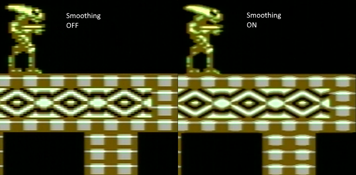
Mode 3 – Doubling + Smoothing (both LEDs on) – In this mode the RetroTINK 2X will apply an image smoothing filter to the output. This filter can smooth some of the jagged edges that appear in classic video games console graphics output. Setting this option is entirely a matter of taste, there is no right or wrong setting.
The picture below shows an example of how the smoothing filter changes the image.
Status LEDs
There are two banks of small status LEDs on the RetroTINK 2X. The bottom bank indicates the currently active input. The LEDs are labelled "YPbPr" (component video), "Y/C" (S-Video) and "CVBS" (composite video).
These LEDS will blink rapidly for a split second when the RetroTINK is first powered on. If they continue to blink rapidly this indicates an error. Check the source signal and power cycle the RetroTINK 2X.
The top bank of LEDs are labelled "2X" and "FIL". If all of these LEDs are extinguished, the RetroTINK 2X is in transcoding only mode. If the 2X LED is lit, the RetroTINK 2X is in line double mode and any valid signal fed into the unit will be line doubled. If the "FIL" light is lit, the smoothing filter will also be applied. Note that it is not possible to use the smoothing filter in transcoding only mode.
Compatibility and special configuration
RetroTINK 2X is not a complex device and indeed there aren't many settings which can be changed. If there are any special compatibility steps which need to be followed they will be documented here.
Displays with reported compatibility problems
Some displays have reported compatibility problems with the RetroTINK 2X. While this list should not be considered definitive until an entry has been confirmed by several users, you should nevertheless be cautious if buying a RetroTINK 2X specifically for use on one of these displays.
| Display | Problem | Reported by |
|---|---|---|
| Philips 32PLF5322/10 | Audio does not work | VGP Customer |
| Samsung QE75Q7FAMTXXU | Completely incompatible | VGP Customer |
Modded PAL consoles
Several users have reported that PAL consoles modded for 60hz may be incompatible with the RetroTINK 2X. Particularly the PAL Sega Master System appears to have issues. Note: the new firmware now fully supports PAL-60.
RetroTINK 2X and OSSC
There has been considerable interest in using the RetroTINK 2X with the OSSC. Since the OSSC does not support composite or S-Video natively, the RetroTINK 2X can be used as a transcoder to enable these types of signals on the OSSC.
The recommended procedure is to utilize a HDMI to component video transcoder [[1]] for connecting the RetroTINK 2X to the OSSC. This allows for the use of the OSSC's LPF to eliminate the pixel edge jitter effects observed with the VGA adaptor.
A video demonstration can be found here [[2]]. Settings that have been found to work well:
- RetroTINK-2X set to pass-thru (no line doubling)
- OSSC LPF set to 9.5 MHz
- Generic sampling
Firmware Upgrade
The RetroTINK-2X's PIC32 micro controller can be flashed with new firmware. You will need the a PIC programmer and the TagConnect cable:
- [[3]]
- [[4]]
Programming Procedure:
- Unscrew the top side of the 2x plastic enclosure.
- Install the MPLAB software
- Insert the PIC programmer to your PC's USB port
- Power up the RetroTINK-2X
- Insert the TagConnect cable into the PIC programmer. The header will have black mark on the side which corresponds to pin 1 (marked by a triangle on the PICKIT)
- Start the MPLAB IPE software
- At the bottom you'll see 'Hex File:' Click 'Browse' and load the correct HEX file for your PCB revision
- Under device select 'PIC32MX120F032D' and hit 'Apply'
- Under tool it should already say PICkit3 and hit 'Connect'
- Plug the tool into the 2x (you should see a place with 6 contact points)
- Press the 'program' button and wait for the flash update to finish and verify


